
EEV Extension 422
EEV-EXT-422-RTU
Add control and measurement points to an installation driven by a PLC, a SCADA system or an EEV controller. The module connects as a slave on a Modbus RTU (RS-485) bus and mounts on a DIN rail, inside a cabinet.
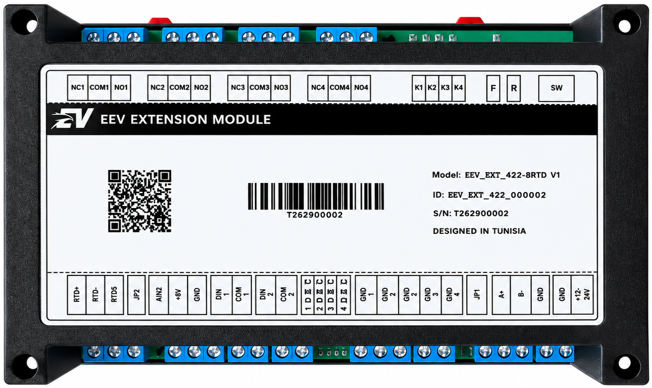
Terminal markings
The markings below follow, face by face, the silkscreen printed on the module label.
Top face — relay outputs
Bottom face — inputs, bus and power
What the module adds
4
relay outputs
SPDT dry-contact changeover — NC / COM / NO terminals, 3 A at 250 V AC, with a fallback state configurable per output.
2
analogue inputs
RTD1 for PT100 / PT1000 probes, thermistors and potentiometers; AIN2 for 0-10 V, 4-20 mA and 0-5 V ratiometric.
2
digital inputs
Universal 10 to 30 V, polarity independent, as on/off, 32-bit pulse counter or frequency meter.
4
direct commands
The CMD inputs drive the relay outputs without going through the bus, and keep working when the master is down.
Two independent control paths
Each relay output can be driven by the bus and by a contact wired to the front panel. The priority rule between the two — the arbitration — is configured output by output.
Modbus bus
The master — PLC, SCADA system, controller — writes the desired output state. This is the normal operating path, with logging and remote control.
Direct command input (CMD)
A dry contact acts directly on the matching output. This path keeps working even with the bus cut or the master down: local button, safety pressure switch, manual override.
Use cases
PLC expansion
Add four power outputs and four measurements to a PLC whose I/O cards are full.
Remote I/O
Put the control and measurement points close to the process, and run only a twisted pair back to the master.
Temperature control
A PT100 probe on RTD1, a heating element on a relay, and a local loop that survives the loss of the bus.
Metering
Count the pulses of a water or energy meter and report them to the master.
Specifications
- Power supply
- 12 to 24 V DC (30 V max) — SELV / PELV
- Consumption
- < 1.5 W idle, ≈ 3 W with all relays closed
- Relay outputs
- 4 SPDT changeover — 3 A at 250 V AC (750 VA)
- Relay isolation
- 1,500 V AC between contacts and coil
- Analogue inputs
- 2 dedicated — RTD1 and AIN2
- Digital inputs
- 2 universal 10 to 30 V, polarity independent
- Command inputs
- 4 direct, self-powered dry contact
- Fieldbus
- Modbus RTU slave over RS-485 — 9,600 to 115,200 baud
- Addressing
- 1 to 247, assigned from the master (no DIP switch)
- Terminals
- Screw, 5 mm pitch — 0.2 to 2.5 mm² (24 to 12 AWG)
- Mounting
- 35 mm DIN rail (EN 60715)
- Environment
- −20 °C to +60 °C, 5 to 95 % RH non-condensing — IP20
This module is a wired fieldbus device: it has no mobile app, no radio connectivity and no online service, and therefore requires no subscription. It must be installed exclusively in a closed electrical cabinet or enclosure, by qualified personnel — read the user manual before any work.
Documents
Documents →- PDF
Quick start guide
EEV_EXT_422_RTU_quick_start_v1.0.pdf
- PDF
User manual
EEV_EXT_422_RTU_user_manual_v1.0.pdf